Company
The Axsys Advantage
Financing & Promotions
Product Portfolio
Dental Machining Centers
VERSAMILL 5 SERIES
VERSAMILL SPEED 3 SERIES
VERSAMILL SPEED 7 SERIES
Chairside Machining Centers
Consumable Products
News & Testimonials
Company
The Axsys Advantage
Financing & Promotions
Product Portfolio
Dental Machining Centers
VERSAMILL 5 SERIES
VERSAMILL SPEED 3 SERIES
VERSAMILL SPEED 7 SERIES
Chairside Machining Centers
Consumable Products
News & Testimonials
Four Key Elements in a Digital Manufacturing System that directly affect Machine Performance, Machine Reliability and Restoration Quality
Key Elements to Dental Manufacturing Quality Element: Machine Design
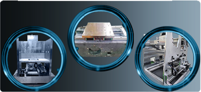
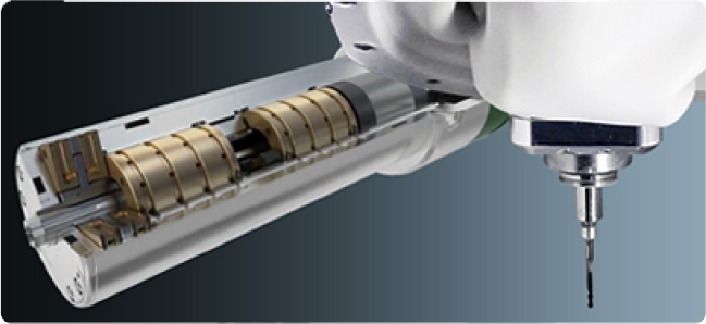
To achieve optimum performance and reliably produce restorations of the highest quality, a CNC milling machine must be constructed to keep heat and vibration to a minimum.
Due to high spindle speeds and cutting rates cutting forces and heat increase leading to higher deflections, thermal deformations and vibration of the machine resulting in accuracy deterioration.
To achieve the required high operating bandwidth while maintaining relatively high accuracy, the structure of CNC machine tool must be rigid.
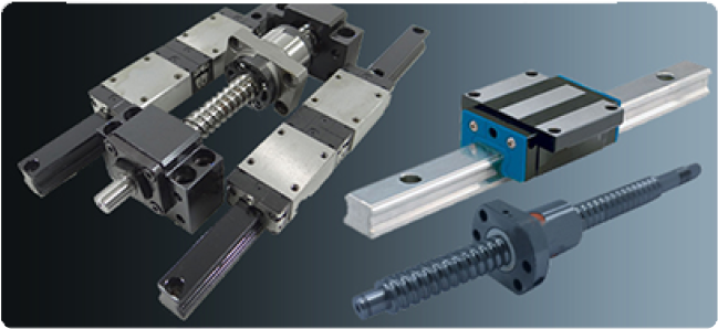
The motion control system is responsible for moving the machine in a controlled manner. Motion control may be open loop or closed loop.
In open loop systems, the controller sends a command through the amplifier to the motor, and does not know if the desired motion was actually achieved. Typically these systems utilize stepper motors for control.
For tighter control with more precision, a measuring device (such as an encoder or glass scale) may be added to the system. When the measurement is converted to a signal that is sent back to the controller, and the controller compensates for any error, it becomes a Closed loop System.
Open loop systems are subject to position errors caused by mechanical interfaces and tolerances, spindle overload and stalling, power spikes and a host of other conditions.
A direct consequence of positioning errors is the requirement to “calibrate” the machine to reestablish true position within the system, which is typically done daily or in high-production applications or lower quality machines, multiple times per day.
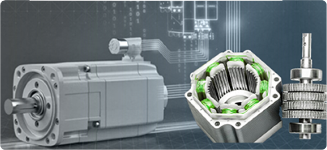
Closed loop, servo-driven systems are the preferred system in applications requiring precise control, very swift response to commands and exact fidelity to position commands
Key Elements to Dental Manufacturing Quality
Element: Jigs & Fixtures
Use of zero stack tolerance machine jigs & fixtures that fully support the part and part rough stock to assure the best possible restorations, minimize tool wear, and eliminate re-makes.
The Importance of Proper Fixturing
The quality and performance of a dental machining center are heavily influenced by jigs and fixtures, as they are responsible for the placing and holding of a component.
Good jigs and fixtures provide dental manufacturing professionals the following:
Some of the advantages associated with a good jig and fixture include:
Productivity
Good jigs and fixtures are able to effectively increase productivity. This is because the part, during manufacturing, does not have to be frequently checked and eliminates the need for individual marking and positioning.
Costs
Because of increased productivity, a reduction in waste material, a lesser use of manual labor, and the easy assembly offered through using precision machining technologies, the cost of production is considerably reduced.
Skills
The need for a skilled work force to position tools correctly is severely minimized, as the locating, clamping, and correct positioning of the workpiece are done by tool-guiding elements. Semi-skilled operators can be employed.
Quality
The variability of dimensions in mass production cycles is lower, as good jigs and fixtures limit vibration and are able to maintain a quality that is consistent.
Tolerance Stack
A tolerance stack is a calculation to determine how tolerances accumulate. Stacks help establish and optimize part tolerances and ensure that parts are designed to promote maximum function and produce accurate, repeatable results.
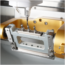
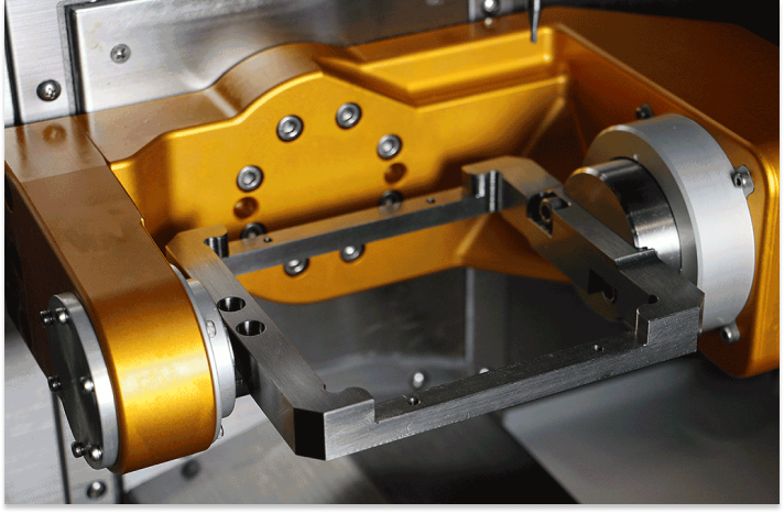
The Versamill’s zero stack tolerance rotary drive alignments and Universal Fixturing System provide complete stability and versatility. Notice the fully supported fixture held on both ends with precision cartridge inserts to enable quick change-over to different rough stock forms (i.e., CAD/CAM discs, pre-form/LiSi blocks, etc.).
Tolerance stackups are vital to address mechanical fit and mechanical performance requirements. Mechanical fit means that the parts that make up the assembly always go together and mechanical performance requirements would include the performance of mechanisms like linear or rotary actuators (axis drives), alignments, latches, etc.
High-quality fixtures account for certain sources of variation in the manufacturing process, such as:
Custom Jigs & Fixtures
Designed and Manufactured to the
Highest Quality Standards
We designed and manufactured a completely new stainless steel fixture to a tighter tolerance than the stand-arum fixture. This results in reduced vibration and consistent quality that is considered to be the finest of any custom abutment produced by any solution on the market.
The CAM software must output smooth motion utilizing specialized high-speed machining strategies that will minimize machine time and increase cutting tool life while providing fine, highly detailed surface finishes with the best restorative margins.
There are many components to an effective high-speed machining process for the fabrication of dental prostheses. Although much has been written about the impact HSM (High Speed Machining) has had on CNC machine tools, spindles, tool holders, cutting tools, and machine controls, often forgotten is the high speed machining impact on tool path programming techniques and the CAM software that creates them.
CAD/CAM technology is evolving today to meet the specific needs for new tool path strategies to suit the HSM environment—the use of higher spindle speeds and feed rates to remove material faster without a degradation of part quality. The goal is to finish dental restorations to net shape, to improve surface finish and geometric accuracy so that hand-finishing can be reduced or eliminated.
Basic Requirements
The challenge to the CAD/CAM system is to create smooth, error-free motion consisting of machining passes with very small step-overs at very high feed rates. This motion must be accomplished without overloading the cutting tool, forcing the tool to make sharp turns, and with minimum entry and exits into the cut. A given toolpath for high-speed milling has to satisfy a number of constraints.
High-speed machining offers the opportunity to significantly increase quality, reduce machining times, and minimize manual rework for complex shapes common to the dental industry. To achieve the best results, it is necessary to apply HSM-suitable machining strategies to perform optimal high-speed milling operations.
By examining the geometrical and topological information of the workpiece’s virtual model, the feature elements can be evaluated. This covers several important high-speed cutting aspects in the CAM system, like optimal technology, strategy selection, and the process stability of different strategies.
For anything but the simplest parts, HSM will involve several machining steps. Choosing the right machining sequence is the most important stage of HSM programming and one where software capability is most valuable.
The level of automation is increasing steadily in dental CAM software, but in the end, the quality of the final restoration is in a large part determined by the availability, use, quality, and robustness of the available strategies provided by the software.
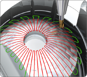
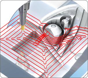
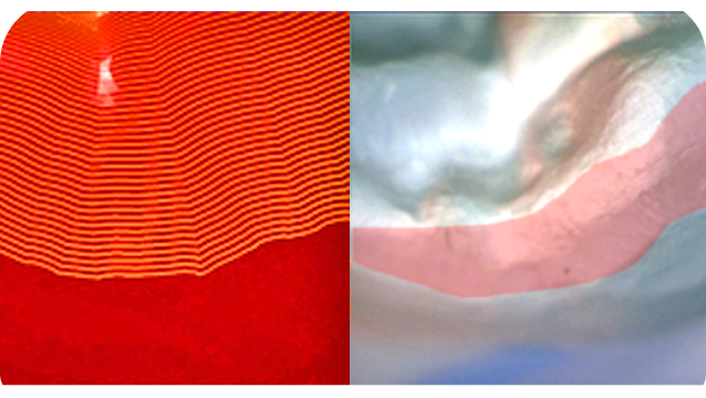
Depending on the part shape, Raster, Radial or Spiral strategies can be employed to provide maximum efficiency. Full control of the leads and links ensures smooth toolpath transitions, improving both tool life and surface finish.
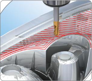
3D offset machining delivers an excellent surface finish because the step-over is varied to give a constant cusp height, both on steep surfaces and shallow contoured areas.
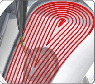
Spiral offset finishing prevents ‘witness marks’, reduces machining time and improves tool life since the tool stays in constant contact with the model in one smooth spiral motion, giving an excellent surface finish
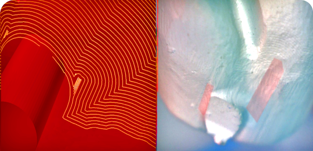
Intelligently removes small islands of residual stock that can remain on the part due to a combination of tool radii and step-over by inserting a smooth extension into the area.
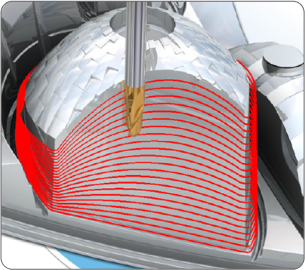
3D Offset and Constant-Z finishing are combined to produce the best toolpaths for machining both the flatter and steeper areas of a part. Here the strategy automatically interleaves the toolpaths in the intermediate areas between the two strategies, ensuring high surface quality.
Parametric Offset machining intelligently morphs toolpaths across a surface with a varying rather than constant step-over. This strategy covers the complete area without any sharp changes in direction, improving surface finish and tool life.
The main requirements of high-efficiency roughing are to keep the load on the cutter as constant as possible and to minimize any sudden changes in the cutting direction
Pencil milling automatically cleans up corners or concave fillets so that there is uniform stock left at surface intersections. Relieving the larger volume of material allows for less tool deflection and noise when cutting corners.
STL files are widely used as the data source from which to represent the restoration to be fabricated and from which to plan a tool path. However, an STL file is like a bucket of random facets—the facet data in the STL file is unordered and no topological information is provided.
First, an efficient data structure must be employed to organize the STL data because subsequent operations (such as data query and geometry feature calculation, the tool path generation, etc.) query facet geometry information frequently.
Methods must also be established to represent the topology information of STL files, calculate local geometry information, generate toolpath points at non-vertex model points, and check for interference. There are many techniques that can be used, all of which are complicated to implement and directly affect computation time, strategy robustness, and quality of the final toolpath that creates a restoration.
It is important to compare the actual output generated from different dental CAM software products to determine which one consistently provides the highest quality output based on their internal methods and software algorithms.
In addition to the dedicated strategies, toolpaths can be enhanced with toolpath and tool-axis editing, feedrate optimization, and improved point distribution. Intelligent point distribution along the toolpath ensures programs are optimized for your machine control and machine configuration, ensuring the smoothest surface finish, fastest cycle times, and highest accuracy.
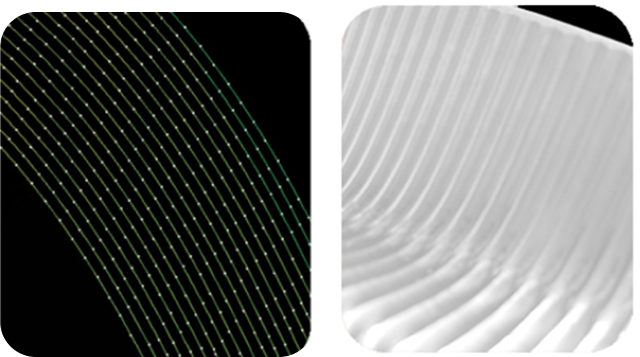
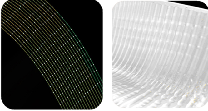
Consequences of Random Point Spacing & Erratic Tool Motion
The majority of dental CAM software solutions have limitations in key areas that have serious impact on restoration quality, including:
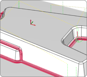
Irregular Machine Containment boundaries.
Always show up in the finished restoration.
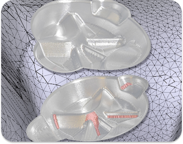
Fragmented toolpath & on-surface approach & retract moves
Violates restoration geometry requiring manual benchwork.
Fragmented toolpath & on-surface approach & retract moves
Violates restoration geometry requiring manual benchwork.
Below is an example of three crowns produced from three different CAM software solutions. These crowns shared a common STL model file and were machined on the same milling machine.
Intelligent & fully automated
The Basics
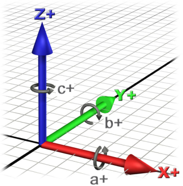
Generally speaking, 5-Axis machining is a manufacturing process where computer numerically controlled axes moved in 5 ways are used to manufacture parts out of metal or other materials by milling away excess material. Typical CNC tools support translation in 3 axes; multi-axis or 5-axis machines also support rotation around one or multiple axes. The number of axes for multi-axis machines varies from 4 to as many as 9. Each axis of movement is implemented either by moving the table (into which the workpiece is attached) or by moving the tool. The actual configuration of axes varies; therefore, machines with the same number of axes can differ in the movements that can be performed. 5-axis machining can be broken down into two different categories: full, simultaneous 5-axis machining and 3+2 5-axis machining
Highly efficient machining templates must be available to achieve maximum machine and tooling performance
without compromising quality and machine operational reliability.
High-speed machining (HSM) contributes greatly in the manufacturing of dental prostheses. With high-speed machining, complex contour shapes can be machined so accurately that little or no finishing operation is necessary. High-speed machining offers a practical way to minimize cutting force and therefore minimize workpiece deflection.
It is the machining template library that ultimately maximizes the effectiveness of high-speed machining by creating the output to work within the CAM software’s core technology and the machine’s capability to produce the best possible restorations in the shortest time possible with the minimum of post-machining bench work.
Our “knowledge-based” system is based on specific knowledge of various aspects of high-speed machining, such as machining parameters, cutting tool materials, chip formation, stability analysis during high-speed machining, etc. Cutting parameters are selected to maximize machining performance based on cutting tool materials for different combinations of cutting speeds and workpiece materials. It takes into account stability analysis during high-speed machining for the manufacturing of restorations fabricated from a wide variety of hard and soft materials.
Axsys Dental Solutions is unique as our templates incorporate a wide range of effective high-speed machining techniques based on over 40 years of experience in working with small and large companies in the automotive, aerospace, die/mold, and machine tool industries. Selection criteria include: