Company
The Axsys Advantage
Financing & Promotions
Product Portfolio
Dental Machining Centers
VERSAMILL 5 SERIES
VERSAMILL SPEED 3 SERIES
VERSAMILL SPEED 7 SERIES
Chairside Machining Centers
Consumable Products
News & Testimonials
Company
The Axsys Advantage
Financing & Promotions
Product Portfolio
Dental Machining Centers
VERSAMILL 5 SERIES
VERSAMILL SPEED 3 SERIES
VERSAMILL SPEED 7 SERIES
Chairside Machining Centers
Consumable Products
News & Testimonials
Provides Greater Accuracy,Higher-Quality Finishes
& Reduced Hand-Finishing.
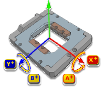
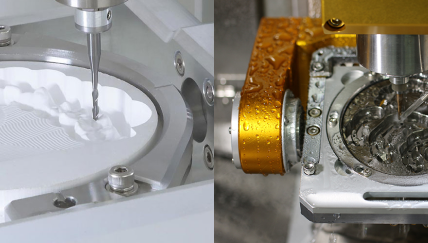
In simultaneous 5-axis machining, the machine tool’s three linear axes (X, Y, and Z) and two rotational axes (A and B) all engage at the same time to perform complex contour surface machining, particularly important in the finish machining of undercut areas. There are many advantages of full 5-axis machining, all of which significantly impact finished product quality, productivity, and profitability.
Not all machines or CAM software supports simultaneous 5-axis motion
nor do all restorations require it.
Fixed motion, or 3 + 2 machining, is a technique whereby a three-axis milling program is executed with the cutting tool locked in a tilted position using the five-axis machine’s two rotational axes, hence the name, 3 + 2 machining. It is also called “positional five-axis machining” because the fourth and fifth axes are used to orient the cutting tool in a fixed position rather than to manipulate the tool continuously during the machining process.
Useful as this type of motion:
Common applications for 3 + 2 operations include roughing and other aggressive high-speed machining techniques.
FixA number of CAM software suppliers have developed special utilities to create tool paths for 3 + 2 or simultaneous 5-axis machining. Not all five-axis programming software includes provisions for both techniques. Like all software capabilities, ease of use and effectiveness of 5-axis machining utilities vary in each CAM software solution.
Utilities for 5-axis machining also vary according to the level of automation available within the automated machining templates provided by the machine manufacturer or distributor. Establishing the workplane and machining zones; setting travel limits for cutting tool motion; and controlling the tool angle are some of the steps that might be more or less automated, depending on the system.
Almost all CAM software suppliers that offer multi-axis machining for five-axis machines emphasize the importance of effective collision avoidance. Potential users should evaluate the collision avoidance and program simulation capabilities of the CAM software being offered.
Beyond the type of 5-axis motion that is supported, the effectiveness and resulting restoration quality and tool life are governed by drive construction characteristics (such as fixture configuration, rotary axis stack and gearing) as well as actual drive rotational limits
Generally, the two rotary axes that comprise a 5-axis machine are the A-axis, which rotates around the linear X-axis, and the B-axis, which rotates around the linear Y-axis of a machine. Depending on configuration, one of the rotary axes should provide a full 360 degrees of rotation, while the other will be limited to an angular range. The limits of this rotational axis are governed by internal construction characteristics and, in large part, geometry and the machine’s external components, such as fixture configuration, coolant nozzles, spindle geometry, Z-axis head dimensions, and the like.
Although a machine manufacturer may provide a specification for theoretical rotary axis operational range, in practical terms it is likely other elements will limit its actual range, which may limit its use, or in some cases, without sufficient CAM software collision detection or verification capability, result in machine, part, and tool mechanical interference, potentially causing damage to all involved elements.
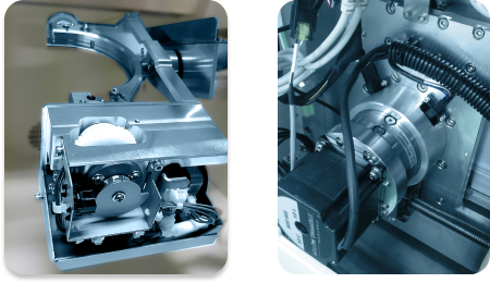
A gear reduction drive assembly is utilized to provide the required power to a 5-axis machine’s rotary axes by changing the ratio of the rotation of two moving parts. The performance of the machine’s rotary drives is in large part determined by this reduction drive. Key factors to consider include:
The interface between the motor and the axis rotary assembly must be of high precision and made of high-strength materials with high resistance to wear and slippage.
Compare on the right the Versamill’s heavy-duty gear reducer constructed from high-strength steel with the vibration-prone, light-weight rotary drive assembly typical of competitive solutions.
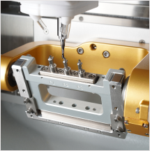
Fixtures should be of high precision, constructed of high-strength steel, and be fully supported on both ends to assure accuracy and eliminate vibration to provide complete stability. Good jigs and fixtures provide:
Compare Versamill’s fully supported fixture on the right with that of the partially supported fixture utilized on a popular competitive solution.
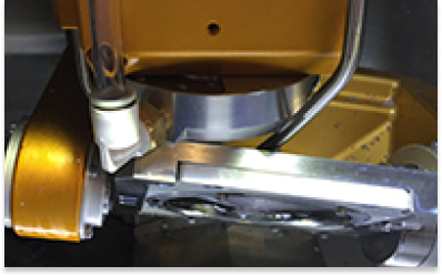
The typical rotary configuration utilized in dental milling machines consists of a trunnion with an “A”- and a “B”-axis part rotation assembly mounted in the XY plane. In order to facilitate multi-axis motion, it is necessary to “stack” each additional axis on top of another.
As the “stack increases, achieving stability and dynamic accuracy becomes extremely difficult.
Compare the Versamill’s zero stack tolerance rotary configuration on the right with the extreme configuration found in a competitive solution.